5 blend create a sheet metal wall by blending several sections sketched in parallel planes as shown in figure sm 10.
Creo 2 sheet metal bend.
In the creation.
When unbending a sheet metal part creo parametric now picks a surface to remain fixed by default which makes the process much faster and easier to use.
In annotate tab select show annotations icon.
In an open sheet metal part with bends click flexible modeling edit bend.
Symmetrically opposite sheet metal part bend other direction i did a quick video from a test that worked better than expected.
I know you don t have creo 2 0 but your version should work the same way.
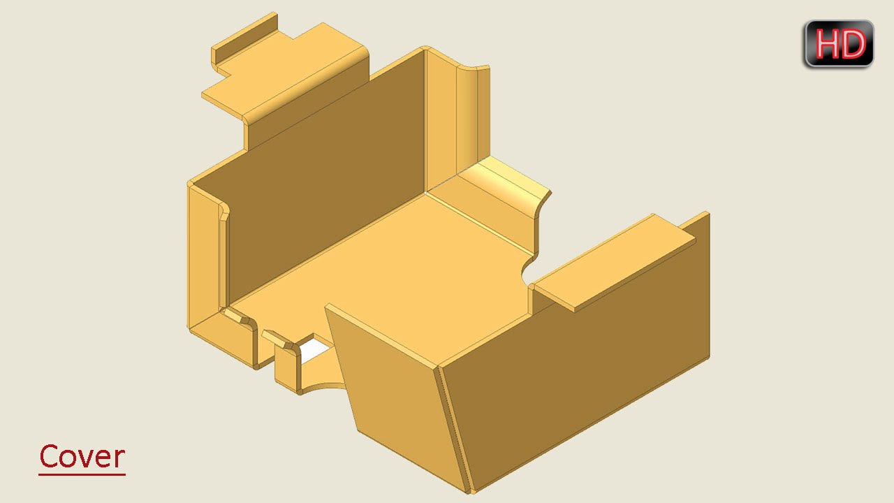
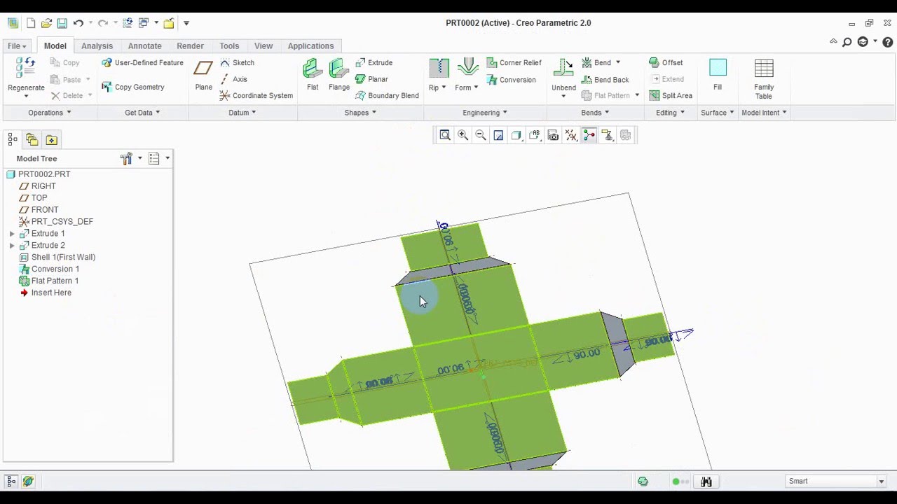
In this tutorial we will learn about the basic techniques related to sheet metal functionality of creo parametric by modelling a cover.
I don t know what you re actual geometry is but i m not sure we are talking about the same thing.
Now select bend order select the bends one by one if it is difficult to select bend switch to wireframe view.
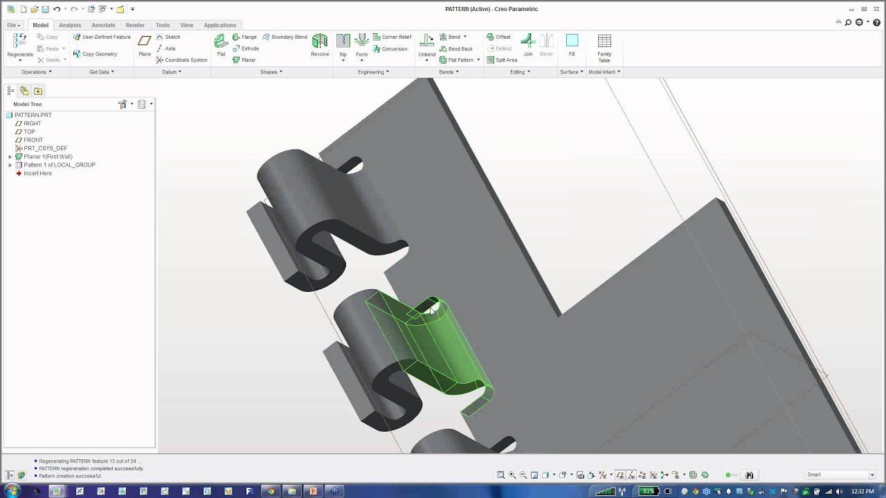
How to create sheet metal bend through flat area.
Open drawing sheet place flatten view.
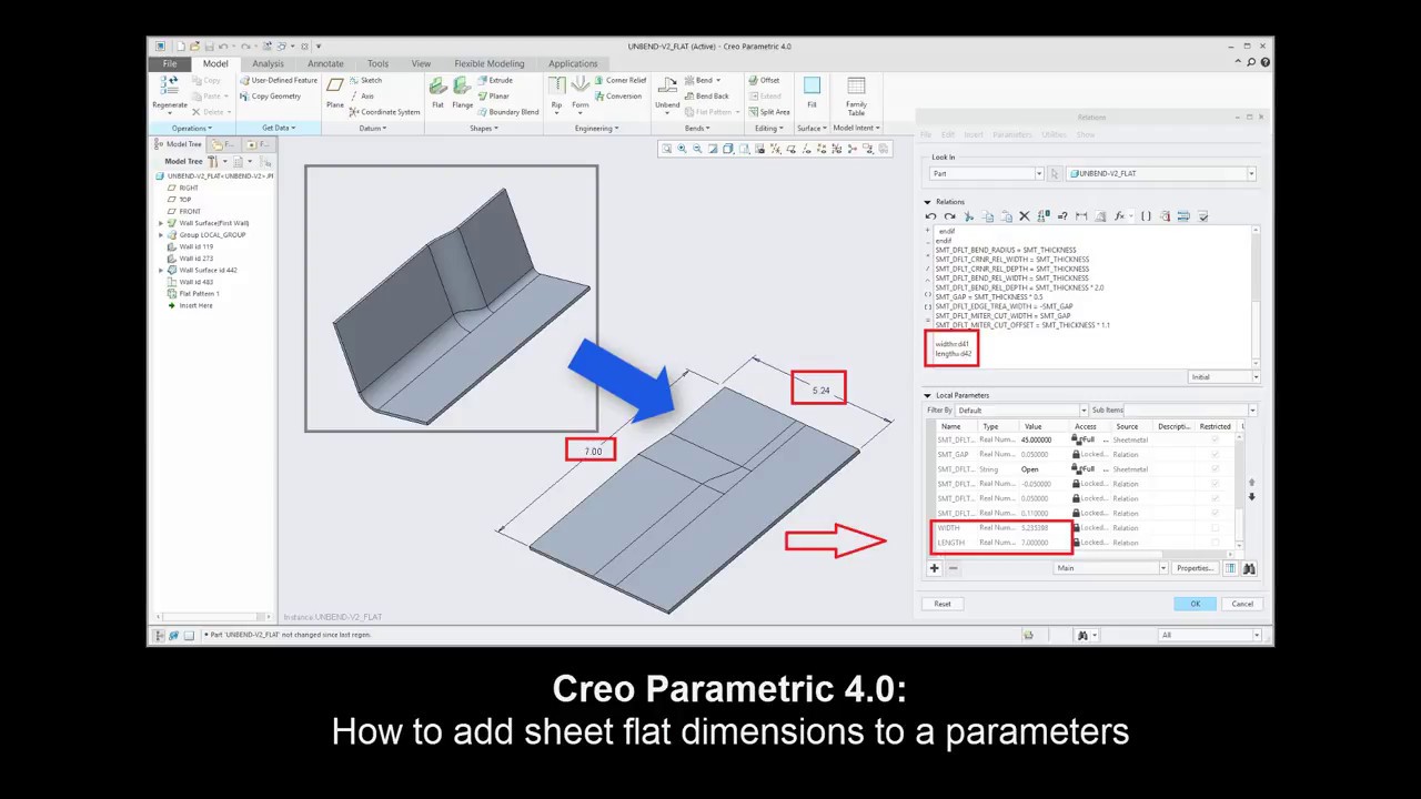
Using a variety of y and k factor bend allowance calculations designers can create flat patterns of the designs.
A different surface can also be selected to remain fixed by clearing the default surface.
Figure sm 10 base feature blended wall flat sketch the boundaries of the wall fig.
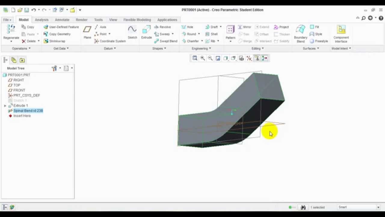
Now that you have a sheet metal part just go to the edit bend command.
Figure sm 12 base feature offset wall.
Now you can use the draggers to change the angle or radius.
Click the options tab to control the length of the wall when you edit a bend.
This allows the user to pick a fixed surface.
The split area splits the driving surface into two or more areas and you then add a bend to the surface you want to bend no need for an additional extrude to refill geometry.
To change the geometry that remains constant during the bend operation select an option from the bend editing option list.
In the options tab.
Figure sm 11 feature flat wall offset create a wall that is offset from a surface fig.
This helps to maintain a consistent fixed surface or edge.
This comprehensive suite of creo sheet metal design tools helps users create features such as walls bends punches notches forms and relief features.
Creo sheet metal training.
Click edit bend in the mini toolbar.
Start by selecting the bend surface.